Breadboard tutorial: learn electronics with Raspberry Pi
By Russell Barnes. Posted

This humble plastic block full of holes can be used to create just about anything
Most of our projects are tested using a small piece of plastic known as a breadboard. Officially, it’s known as a ‘solderless breadboard’ because it enables you to use circuit parts without soldering them together.
Electrical components are connected by pushing them into the holes in a breadboard. These holes are connected in strips, as shown in the main image. If you push a wire, or a different component, into one hole in a strip, and another wire into the hole next to it, it’s as if you’d physically joined (or soldered) the two wires.
Get a free Raspberry Pi with a subscription to The MagPi. Click here for more info,
See also:
- MagPi Essentials: Simple Electronics with GPIO Zero
- The best Raspberry Pi Starter Kits
- Reaction Game: build a circuit game using LEDs, buttons, and a breadboard
- Getting You Started Kit with Raspberry Pi Zero W review
How to use an electronics breadboard with a Raspberry Pi
In the old days, people would either solder wire components together on an actual breadboard, or they’d wrap wires together around nails in a pinboard.
For a lot of Raspberry Pi fans, using a breadboard is part of life. But for many newcomers this quirky piece of kit is baffling: a smorgasbord of holes arranged in rows and columns that seem to make little sense.
So we think it’s high time we had a beginner’s guide to how a breadboard works. In this tutorial, we’ll explain how these holes are arranged, and how to set up a circuit on your breadboard.
If you already know all this, feel free to move on. If not, stick around and learn about one of the most fun things you can do: building your own circuits and hooking hardware up to your Raspberry Pi.
Using a breadboard
- Breadboard
- LED light
- Resistor
- Male-to-female jumper leads
- Male-to-male jumper leads
Create a simple LED circuit with a breadboard
Circuit diagrams can be a little hard to understand for the novice. So we use visual breadboard diagrams, like this. This complete diagram uses the power and ground pins from a Raspberry Pi to light up an LED.

The breadboard’s live rail
Take a female-to-male jumper lead (the colour of the wire doesn’t matter) and connect the female end to a 5V pin on the Raspberry Pi. Place the male end of the lead into a hole on the red rail on the breadboard.

The breadboard’s ground rail
Take another female-to-male jumper and connect the female end to a ground (GND) pin on the Raspberry Pi. The male end goes into a hole on the blue (ground) rail. All blue holes now act as a ground pin.

Add a resistor to the breadboard
Take a resistor and connect one leg of it to a hole on the ground rail of the breadboard. It’s now linked to the ground pin of the Raspberry Pi (via the jumper lead we used in the previous step). Take the other leg and connect it to a hole on the main breadboard.

Add the LED to the breadboard
Take an LED component and look at the legs. Notice that one of the legs is shorter than the other. Place the shorter leg in a hole on the same row as the resistor. This leg is now connected to the resistor (which is linked to the ground rail, and therefore to the ground pin on the Raspberry Pi).

Wire up the breadboard
Place the longer leg in a hole on the next row along. Now take another male-to-male jumper lead and place one end in the hole next to the long leg of the LED. Place the other end in a hole on the red live rail to complete the circuit. The LED lights up.


Russell runs Raspberry Pi Press, which includes The MagPi, Hello World, HackSpace magazine, and book projects. He’s a massive sci-fi bore.
Subscribe to Raspberry Pi Official Magazine
Save up to 37% off the cover price and get a FREE Raspberry Pi Pico 2 W with a subscription to Raspberry Pi Official Magazine.
More articles
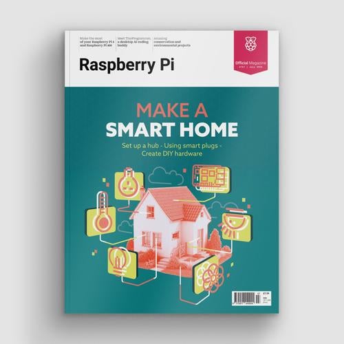
Make a Smart Home in Raspberry Pi Official Magazine issue 167
The dream of smart, connected devices controlling your home automatically, is especialy appealing on a lazy day when we’re trying to get work done in a heatwave. Maybe this will be the year we finally integrate temperature sensors with fans and a drinks dispenser to keep us cool, or maybe not, but we do know […]
Read more →
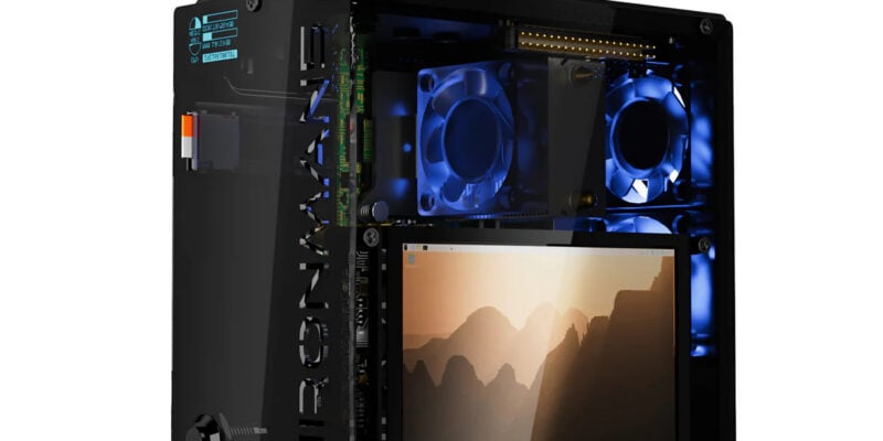
Win 1 of 3 Pironman 5 Pro Max cases!
Transform your Raspberry Pi with this amazing case
Read more →

Learning to code in an AI age
A new Raspberry Pi Foundation course helps young people learn to code.
Read more →