PCB love – making circuit boards
By Drew Fustini. Posted
This article was originally published as part of HackSpace magazine, which has since been incorporated into Raspberry Pi Official Magazine.

You made your first LED blink, you learned how to use a breadboard, and you know which end of the soldering iron to hold. So what’s next? High up on the list of essential electronics skills is learning how to design and make your own printed circuit board (PCB). My first PCB was a POV (persistence of vision) display, a modified version of an Adafruit open hardware design. I still remember how exciting it felt to open up my mail and solder a board I designed myself!
A PCB is a board with traces (lines) that connect different pads or holes for electronic components to each other, or to connectors that allow us to hook up power, microcontrollers, or other parts. We use solder to connect the pads or holes on the bare board to the component that the board was designed for. Once the components are in place, the traces let us push power or data around our boards.
PCBs themselves are like a sandwich made up of layers of different materials. The main ‘body’ of a PCB is made of some kind of substrate; typically a fibreglass called FR4. On top of that is a thin layer of copper-foil that lays out the traces and pads, then a layer of coloured solder mask which prevents solder from sticking where it shouldn’t.
This solder mask is often green, but you can get all sorts of colours, such as my favourite – purple. The copper that is not covered by solder mask then gets protected by a surface finish such as HASL (solder) or ENIG (gold plating). Finally, there is the silkscreen layer where text and symbols are printed.
Like any good sandwich, you can keep adding in more layers of copper, from two layers up to tens of layers. It’s also worth knowing that rigid fibreglass isn’t your only option: you can choose a material called Kapon (polyimide film) to make flexible PCBs. You can even make your PCB sandwich using both fibreglass and Kapon to make a board that is flexible in some places and rigid in others. One super-cool option, that both OSH Park and Evil Mad Scientist Laboratories have been using recently, is black fibreglass paired with a clear solder mask, so all your copper traces are visible.
In next month’s column, I’ll be talking about the awesome ways the hardware hacker community has been using PCB design to make cool electronics projects and beautiful art, as well as sharing some of the tools they’re using to make their boards. In the meantime, I recommend this excellent video that visualises the composition of a PCB: hsmag.cc/SI2m31 (How do PCBs Work? by Branch Education).

Drew Fustini is a hardware designer and embedded Linux developer. He is the Vice President of the Open Source Hardware Association, and a board member of the BeagleBoard.org Foundation.
Subscribe to Raspberry Pi Official Magazine
Save up to 37% off the cover price and get a FREE Raspberry Pi Pico 2 W with a subscription to Raspberry Pi Official Magazine.
More articles
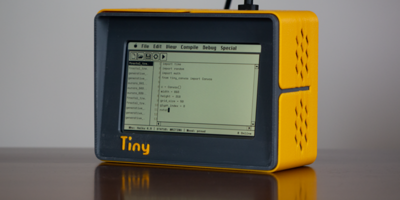
TinyProgrammer
Want a coding companion? TinyProgrammer lets you watch as it tinkers with Python all day. Sean McManus finds out how it works
Read more →
Make a Smart Home in Raspberry Pi Official Magazine issue 167
The dream of smart, connected devices controlling your home automatically, is especialy appealing on a lazy day when we’re trying to get work done in a heatwave. Maybe this will be the year we finally integrate temperature sensors with fans and a drinks dispenser to keep us cool, or maybe not, but we do know […]
Read more →

Win 1 of 3 Pironman 5 Pro Max cases!
Transform your Raspberry Pi with this amazing case
Read more →